Introduction
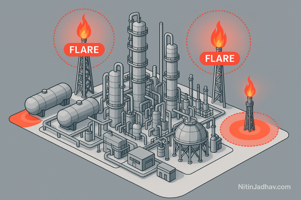
In the oil and gas industry, safety remains a top priority. One of the most critical safety studies undertaken during the design and operation of process facilities is the Flare Radiation and Vent Dispersion Study. This study helps evaluate the potential impact of flaring or venting operations on people, equipment, and the environment. Using advanced modeling tools like FLARESIM and PHAST, engineers can accurately assess thermal radiation, gas dispersion, and the extent of hazardous zones.
This article presents a detailed, SEO-optimized overview of Flare Radiation and Vent Dispersion Studies, covering their purpose, methodology, tools used, industry standards, case studies, and design best practices.
What is Flare Radiation and Vent Dispersion Study?
Flare Radiation and Vent Dispersion Studies aim to assess:
- The thermal radiation intensity generated by flares.
- The gas dispersion behavior of flammable or toxic releases from vents.
The goal is to determine whether these physical effects pose a threat to:
- Manned areas (control rooms, operator shelters).
- Equipment air intakes.
- Critical instruments or structures.
- Fence line receptors or nearby communities.
Objectives of the Study
- Identify potential hazards due to thermal radiation or toxic dispersion.
- Determine safe operating limits for flares and vents.
- Ensure regulatory compliance (OISD, API 521, NFPA, etc.).
- Support design optimization for flare stacks, vent systems, and plant layout.
- Establish exclusion zones and protection measures.
Tools Used for FLARE and Vent Dispersion Studies
1. FLARESIM
FLARESIM is a specialized tool used to calculate:
- Flare radiation (incident heat flux).
- Flame length and height.
- Visible flame envelope.
- Impact on personnel and structures.
Key Outputs:
- Radiation contours (kW/m²).
- Maximum allowable occupancy duration (based on threshold limits).
2. PHAST (Process Hazard Analysis Software Tool)
PHAST models:
- Flammable and toxic gas dispersion.
- Jet and pool fires.
- Overpressure effects.
- Flash fire and explosion envelopes.
Use Case:
- Applied in vent scenarios, especially during relief discharge, line purging, or system blowdowns.
Standards and Guidelines Referenced
- API 521: Guide for Pressure-relieving and Depressuring Systems.
- OISD-STD-116: Guidelines on Layout and Spacing for Oil and Gas Installations.
- NFPA 59A: Standard for the Production, Storage, and Handling of Liquefied Natural Gas.
- ISO 23251: Pressure-relieving and Depressuring Systems.
Thermal Radiation Thresholds
| Exposure Type | Radiation Limit (kW/m²) | Description |
|---|---|---|
| Personnel Movement | 1.6 | Max for safe escape or movement |
| Personnel Work | 4.0 | Max for intermittent exposure |
| Equipment Surface | 9.5 | Limit before equipment coating damage |
Vent Dispersion Criteria
| Criteria | Value/Description |
|---|---|
| Flammable Gas LEL | 100% LEL |
| Toxic Threshold (H2S) | 10 ppm (as per ACGIH TLV) |
| Impact Radius | As per dispersion modeling result |
Methodology of Study
Step 1: Define Scenarios
- Normal flaring
- Emergency depressurization
- Blowdown scenarios
- Venting during purging or maintenance
Step 2: Data Collection
- Flare stack design
- Relief rates and compositions
- Vent line geometry
- Meteorological data (wind speed, stability class)
Step 3: Modeling Using FLARESIM/PHAST
- Input parameters in software
- Set modeling boundaries and sensitive receptors
Step 4: Analyze Results
- Evaluate heat radiation on structures
- Determine dispersion cloud reach
- Overlay results on facility layout
Step 5: Recommend Mitigation
- Increase flare height
- Modify vent routing
- Install protective shielding
- Enforce exclusion zones
Case Study: Radiation Impact on Control Room
Scenario: Emergency depressurization results in flaring of hydrocarbon gas.
Input:
- Relief rate: 120 tons/hr
- Flare height: 40 m
- Wind speed: 3 m/s
Result:
- Radiation at control room: 3.2 kW/m²
- Recommendation: Relocate control room or raise flare height to 60 m
Best Practices in Flare Design
- Ensure flare tip selection is appropriate for gas composition.
- Provide sufficient stack height to reduce ground-level radiation.
- Avoid locating manned buildings within the 1.6 kW/m² contour.
- Consider multiple dispersion weather conditions.
- Integrate results into HAZOP, QRA, and layout studies.
Integration with Other Safety Studies
- QRA (Quantitative Risk Assessment): Flare and vent events feed frequency and consequence data.
- HAZOP/HAZID: Use radiation and dispersion results to validate hazard scenarios.
- EERA (Escape, Evacuation, Rescue Analysis): Radiation or gas plumes may impair evacuation routes.
Conclusion
Flare Radiation and Vent Dispersion Studies are vital tools in process safety design and operations. They help prevent severe consequences by ensuring that flaring or venting does not affect personnel, assets, or the environment. With tools like FLARESIM and PHAST, engineers can design safer plants by proactively identifying risks and mitigating them before incidents occur.
Whether you are designing a greenfield facility or modifying a brownfield installation, incorporating Flare and Vent Studies as part of your safety framework enhances reliability, ensures compliance, and protects lives.