Safety Integrity Level (SIL)
How do we ensure that industrial systems don’t just run—but run safely? In high-risk Industries like oil & gas, chemicals, and power generation, safety isn’t optional—it’s engineered. One of the most powerful tools in our safety arsenal is the Safety Integrity Level (SIL). Whether you’re a design engineer, safety professional, or operations manager, understanding SIL is crucial for building systems that protect people, assets, and the environment. In this post, I’ll walk you through the fundamentals of SIL, how it ties into Safety Instrumented Systems (SIS), and what it takes to design, assess, and certify a system to meet a specific SIL level.
What is SIL??SIL stands for Safety Integrity Level, a discrete level (ranging from SIL 1 to SIL 4) used to define the required performance of Safety Instrumented Functions (SIFs) implemented via Electrical/Electronic/Programmable Electronic (E/E/PE) safety-related systems.
Each SIL level corresponds to a range of probability that a safety system will perform its intended function properly when required. These levels are used to ensure that the risk of failure is reduced to an acceptable level, as determined through a formal risk assessment process.
· SIL 1 represents the lowest level of safety integrity.
· SIL 4 represents the highest, offering the greatest risk reduction, though it is rarely used in process industries due to the extreme cost, complexity, and stringent design requirements involved.
The appropriate SIL rating is assigned based on the severity of the hazard, the likelihood of occurrence, and the ability to detect and respond to the hazard. It reflects the level of risk reduction that the safety system must provide in order to achieve tolerable risk.
What is SIS (Safety instrumented System)???A Safety Instrumented System (SIS) is a critical protection layer designed to detect hazardous conditions and automatically take corrective action to bring the process to a safe state. It performs one or more Safety Instrumented Functions (SIFs), which are specific actions required to mitigate identified risks.
An SIS typically consists of:
· Sensors – to monitor process conditions (e.g., pressure, temperature, flow)
· Logic Solvers – to evaluate inputs and decide on the necessary response
· Final Elements – to carry out the safety action (e.g., shutting a valve or stopping a pump)
In addition to hardware, an SIS may also include:
· Software components that form part of the logic and execution of the SIF
· Human actions, where operator intervention is required as part of the safety function
The SIS is designed and implemented in accordance with the required Safety Integrity Level (SIL), ensuring it meets the necessary reliability and performance criteria for reducing risk to a tolerable level.
Following schematic shows the structure of SIS –
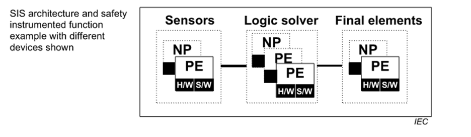
Example of a Typical Safety Instrumented System (SIS):
What is SIL 1, SIL2, SIL3, SIL4?? What’s the Significance of the SIL rating on the SIS?The SIL rating is like the heartbeat of process safety systems. It doesn’t just sit quietly in a document—it actively dictates how reliable, responsive, and risk-resilient the system must be throughout its lifecycle.
🔧 Why SIL Ratings Matter Long-Term
- Lifecycle Assurance: From design through decommissioning, SIL-rated systems are continuously maintained to meet stringent performance standards.
- Failure Prevention: By minimizing the Probability of Failure on Demand (PFD), these systems safeguard against catastrophic events.
- Operational Consistency: They create a stable safety backbone, allowing high-risk industries like oil & gas, chemicals, and power generation to operate with confidence.
- Regulatory Compliance: SIL-based designs ensure adherence to global standards like IEC 61508 and IEC 61511, which are mandatory in many jurisdictions.
And here’s a cool thought: assigning the right SIL isn’t just engineering—it’s risk artistry, balancing safety, cost, redundancy, and real-world failure data to sculpt a solution that truly protects.
Assigning SIL isn’t just about picking a number, it’s about ensuring the safety system is engineered, tested, and maintained to meet that level of reliability. It’s a blend of engineering rigor, statistical modeling, and operational discipline.
Following is the significance of the SIL rating assigned for the Safety Instrumented System –
· SIL 1 – Safety Instrumented System (SIS) with SIL 1 rating are normally implemented with single sensor, a single SIS logic solver and a single final control element. (Ref. IEC-61511)
· SIL 2 – This SIS are fully redundant from the sensor through the SIS logic solver to the final control element. (Ref. IEC-61511)
· SIL 3 – This are typically fully redundant from sensors through logic solver to the final control element and require careful design and frequent proof test to achieve low PFD figures. Many companies find that they have limited number of SIL 3 SIFs due to high cost normally associated with the structure. (Ref. IEC-61511)
· SIL 4 – This SIF’s are included in the IEC 61508 and 61511 standards, but such SIFs are difficult to design and maintain and are not used in the LOPA. (Ref. IEC-61511)
How are SIFs designed as per the SIL rating???Safety Instrumented Functions (SIFs) are designed based on the required Safety Integrity Level (SIL) determined through a risk assessment process. Once the SIL level (SIL 1 to SIL 4) is identified, the SIF must be engineered to meet the corresponding performance and reliability requirements. This includes selecting appropriate hardware and software, ensuring redundancy, minimizing systematic and random failures, and validating the Probability of Failure on Demand (PFD) within the allowable range for the SIL. Higher SIL levels require stricter design, testing, and documentation to ensure the function performs reliably when needed.
Following are the steps for manufacturing the Safety Instrumented System (SIS) with specific SIL level –
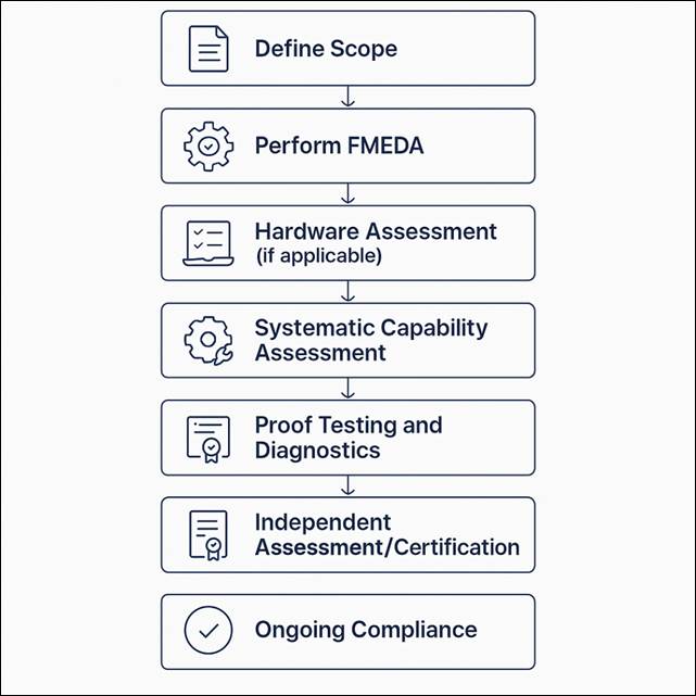
🔹 2. Define Scope
- Identify the product or system to be certified (e.g., pressure transmitter, safety PLC) & define the intended use, operating environment and target SIL level (SIL 1 to SIL 4).
– What is Intended Use?
This defines how and for what purpose the product is meant to be used in a safety context. It includes:
Functionality: What safety function will the component perform? (e.g., emergency shutdown, pressure relief)
Application: In what type of system or industry? (e.g., oil & gas, chemical processing, power generation)
· Mode of Operation:
Continuous – SIF operates in continuous mode when it is constantly active and continuously maintaining a safe state of the process. It is not just waiting for a dangerous condition to occur but is actively controlling or preventing hazards at all times.,
Low-demand – A SIF operates in low-demand mode when it is rarely called upon to act—typically no more than once per year. It remains in a standby state and only activates when a specific hazardous condition arises.
High-demand mode – A SIF operates in high-demand mode when it is expected to respond to hazardous events more than once per year, but not continuously. It is triggered frequently enough that it cannot be considered “low-demand,” but it is not always active like in continuous mode.
– SIL Target: What SIL level is the product expected to support?
✅ Example: A pressure transmitter intended for use in a SIL 2-rated high-pressure gas pipeline shutdown system.
– 🔹 What is Operating Environment?
This refers to the physical and environmental conditions in which the product will operate. It includes:
Temperature range (e.g., -40°C to +85°C), Humidity and moisture, Vibration and shock, Corrosive or explosive atmospheres, Electrical noise or EMI, Indoor vs. outdoor use, Hazardous area classification (e.g., ATEX, IECEx zones)
(✅ Example: A safety relay used in an offshore oil platform must withstand salt spray, high humidity, and vibration.)
– 🔍 Why It Matters
These factors determine the robustness of design and testing protocols. Certification bodies assess whether the product can reliably perform its safety function under these conditions. If the product is used outside its certified scope, the SIL certification may no longer be valid.
🔹 2. Perform FMEDA (Failure Modes, Effects, and Diagnostic Analysis)
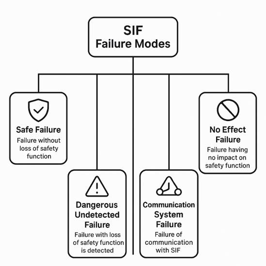
- Analyze all possible failure modes (failure modes help determine how a component or system might fail and what impact that failure could have on safety) of the product.
SIS is a combination of Sensors, Logic Solvers, Actuators, Power supplies and communication. Failure of any one of the components may lead to the hazardous scenarios. Depending on the type of the SIS typical failure modes are as follows –
Typical failure modes by component type are as follows –
Specific Failure Modes of Component Type –
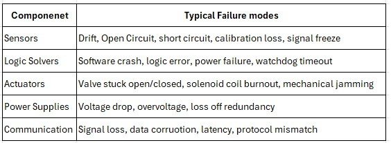
These failure modes are used to calculate PFDavg (Probability of Failure on Demand), Safe Failure Fraction (SFF), Diagnostic Coverage (DC). They help determine whether a component can be used in a SIL 1, 2, 3, or 4 applications.
🔹 3. Hardware Assessment
- Evaluate the hardware architecture: Redundancy (Use of multiple components e.g. Sensors, logic solvers, actuators to perform the same function) Fault tolerance (System’s ability to continue operating correctly even when one or more components fail).
– As per IEC 61508/60511 requirements are –
· HFT = 0: No redundancy (e.g., 1oo1)
· HFT = 1: One failure can be tolerated (e.g., 1oo2)
· HFT = 2: Two failures can be tolerated (e.g., 2oo3)
- Diagnostic features (Built in mechanism to detect internal faults e.g. Sensors Self Checks, Watchdog timers in logic solvers, valve position feedback)
- Ensure it meets the hardware fault tolerance (HFT) requirements for the target SIL.
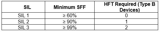
Note: Type B devices are complex (e.g., microprocessor-based), while Type A are simple (e.g., relays).
🔹 4. Software Assessment (if applicable)
- Review the software development lifecycle: Requirements specification Design and coding standards Verification and validation Configuration management
- Ensure compliance with IEC 61508-3 (software-specific part).
🔹 5. Systematic Capability Assessment
- Evaluate the quality management system: Design processes Change control Documentation Training and competence
- This ensures the product is consistently developed and maintained.
🔹 6. Proof Testing and Diagnostics
- Define proof test intervals and procedures.
(Proof Testing is used to detect undetected failure that are not caught by automatic diagnostics. Key elements –
Proof test Interval – The time between two consecutive proof tests.Shorter intervals reduce the PFDavg.
Proof Test Coverage (PTC) – The percentage of dangerous undetected failures that the test can reveal.
Procedure:
- Simulate demand conditions.
- Verify sensor, logic solver, and final element response.
- Document and analyze results.)
Follow IEC-61511 guidelines for proof testing
- Assess the diagnostic coverage and how failures are detected and handled.
(To automatically detect failures during normal operation, especially dangerous detected and safe failures. Diagnostic methods includes –
· Sensor self-checks
· Watchdog timers
· Loop monitoring
· Valve position feedback
· Heartbeat diagnostics (e.g., in smart transmitters)
🔹 7. Independent Assessment / Certification
- Submit all documentation and analysis to a third-party certifying body (e.g., TÜV Rheinland, Exida).
- The certifier performs: Audit of development processes Review of FMEDA and test results On-site inspections (if needed)
🔹 8. Certification Issued
- If all requirements are met, the certifier issues: SIL Certificate (e.g., SIL 2 capable) Safety Manual with: PFDavg values Installation and maintenance instructions Proof test intervals Assumptions and limitations
🔹 9. Ongoing Compliance
- Vendors must maintain: Change management Re-certification after major updates Periodic audits (depending on certifier)
✅ SIL isn’t just a number, it’s a commitment to safety, reliability, and engineering excellence. From defining the intended use to performing FMEDA, hardware assessments, and proof testing, every step in the SIL lifecycle plays a vital role in reducing risk. This article is the first in a series where I’ll continue exploring SIL implementation, LOPA, and real-world case studies.