As in my previous article explanation of Safety Instrumented system, what is the significance of SIL has been provided this 2nd post focuses on the SIL classification study, its importance in the process industry, what are international standards, important terminologies of the SIL classification study are described in this post –
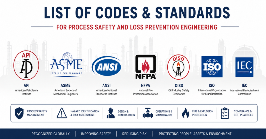
IMPORTANT INTERNATINAL STANDARDS
Important Standards for the SIL Classification –
IEC-61508 –
IEC 61508 is a foundational international standard that defines the framework for achieving functional safety (Part of overall safety that depends on the system or equipment operating correctly in response to inputs particularly in electrical, electronic, or programmable electronic (E/E/PE) systems. It ensures that safety functions are performed reliably and effectively to prevent or mitigate hazardous events.) in electrical, electronic, and programmable electronic (E/E/PE) systems across all industries. It introduces the Safety Lifecycle (step-by-step process that guides the development, operation, and maintenance of safety-related systems to ensure functional safety throughout their entire life) and Safety Integrity Levels (SILs) to manage risk and ensure system reliability. The standard is divided into seven parts, it ensures that safety-related systems are systematically designed, implemented, and maintained to prevent failures that could lead to hazardous events. A short description of all the parts of the IEC-61508 standard is provided further –
🔹 IEC 61508 – Functional Safety of Electrical/Electronic/Programmable Electronic Safety-Related Systems
Scope: Generic standard applicable across all industries using E/E/PE systems.
📘 Part 1: General Requirements
- Establishes the overall framework for functional safety.
- Introduces the Safety Lifecycle and SIL concept.
- Defines risk reduction, hazard analysis, and safety requirements allocation.
📘 Part 2: Requirements for Electrical/Electronic/Programmable Electronic (E/E/PE) Safety-Related Systems
- Specifies requirements for the design and implementation of safety-related systems.
- Covers hardware fault tolerance, systematic capability, and architectural constraints.
📘 Part 3: Software Requirements
- Focuses on software development for safety-related systems.
- Emphasizes software lifecycle, verification, validation, and modularity.
📘 Part 4: Definitions and Abbreviations
- Provides all key terminology used across the standard.
📘 Part 5: Examples and Methods for Determining Safety Integrity Levels
- Offers practical examples and risk graphs, LOPA, and fault tree analysis for SIL determination.
📘 Part 6: Guidelines on the Application of IEC 61508-2 and -3
- Provides guidance and rationale for Parts 2 and 3.
- Helps interpret and apply technical requirements.
📘 Part 7: Overview of Techniques and Measures
- Lists recommended techniques for hardware and software to achieve required SILs.
- Includes design principles, testing, and documentation practices.
🔹 IEC 61511 – Functional Safety for the Process Industry Sector.
IEC 61511 is a sector-specific standard derived from IEC 61508, tailored for the process industry (like oil & gas, chemicals, and pharmaceuticals) to ensure functional safety through Safety Instrumented Systems (SIS). It defines the complete SIS lifecycle, including the development of Safety Instrumented Functions (SIFs), SIL assignment, and creation of a Safety Requirements Specification (SRS). This standard is divided into three parts. The short summary of these parts is provided further –
🔹 IEC 61511 – Functional Safety for the Process Industry Sector
Scope: Tailored for the process industry (e.g., oil & gas, chemicals, pharmaceuticals).
📘 Part 1: Framework, Definitions, System, Hardware and Software Requirements
- Adapts IEC 61508 principles to the process sector.
- Defines Safety Instrumented Systems (SIS) and Safety Instrumented Functions (SIFs).
- Introduces SIL assignment, SRS (Safety Requirements Specification), and SIS lifecycle.
📘 Part 2: Guidelines for the Application of IEC 61511-1
- Offers detailed guidance on implementing Part 1.
- Includes examples, best practices, and interpretations.
📘 Part 3: Guidance for the Determination of the Required Safety Integrity Levels
- Focuses on SIL determination methods like: Risk graphs Layer of Protection Analysis (LOPA) Fault tree analysis
- Helps users justify SIL levels based on risk reduction needs.
🔍 Key Concepts Across Both Standards
- SIL (1 to 4): Indicates the level of risk reduction provided by a safety function.
- SIS Lifecycle: From concept to decommissioning, ensuring safety is maintained throughout.
- Systematic Capability: Ability to avoid systematic failures through good engineering practices.
- Hardware Fault Tolerance (HFT): Redundancy to tolerate hardware failures.
- Proof Testing: Regular testing to ensure the system performs as intended.
IMPORTANT DEFINITIONS
In the industry today, Safety Integrity Level (SIL) analysis is primarily conducted using two widely accepted methods: the Risk Graph Method and the Layer of Protection Analysis (LOPA). The key terminologies associated with each method are outlined below, as a clear understanding of these terms is essential before initiating the study. The definitions are categorized into method-specific terms and common terms applicable to both approaches.
The following are key definitions relevant to both SIL classification methods—the Risk Graph Method and the Layer of Protection Analysis (LOPA). Understanding these terms is essential before proceeding with the SIL study, as they form the foundation for evaluating risk and determining appropriate safety integrity levels.
1. Tolerable Risk (IEC-61508)
Risk which is accepted in a given context based on the current values of society
2. Residual Risk (IEC-61508)
Risk remaining after protective measures have been taken
3. Target Risk (IEC-61508)
Risk that is intended to be reached for a specific hazard considering the EUC risk together with the electrical/electronic/programmable electronic (E/E/PE) safety-related systems and the other risk reduction measures
4. Functional Safety (IEC-61508)
Part of the overall safety relating to the EUC and the EUC control system that depends on the correct functioning of the E/E/PE safety-related systems and other risk reduction measures
5. Redundancy (IEC-61508)
The existence of more than one means for performing a required function or for representing information.
6. Safety Integrity (IEC-61508)
Probability of an E/E/PE safety-related system satisfactorily performing the specified safety functions under all the stated conditions within a stated period of time. Higher the level of safety integrity, the lower the probability that the safety related system will fail to carry out the specified functions or will fail to adopt a specified state when required.
7. Safety Integrity Level (SIL) (IEC-61508)
Discrete level (one out of a possible four), corresponding to a range of safety integrity values, where safety integrity level 4 has the highest level of safety integrity and safety integrity level 1has the lowest
8. Necessary risk reduction (IEC-61508)
Risk reduction to be achieved by the E/E/PE safety-related systems and/or other risk reduction measures in order to ensure that the tolerable risk is not exceeded
9. Probability of Dangerous Failure on Demand (PFD) (IEC-61508)
Safety unavailability of an electrical/electronic/programmable electronic (E/E/PE) safety-related system to perform the specified safety function when a demand occurs from the Equipment Under Control (EUC) or EUC control system
10. Average Probability of Dangerous Failure on Demand (PFDavg) (IEC-61508)
Mean unavailability of an electrical/electronic/programmable electronic (E/E/PE) safety-related system to perform the specified safety function when a demand occurs from the Equipment Under Control (EUC) or EUC control system
11. Process Safety Time (IEC-61508)
The period of time between a failure, that has the potential to give rise to a hazardous event, occurring in the EUC or EUC control system and the time by which action has to be completed in the EUC to prevent the hazardous event occurring
12. Basic Process Control System (IEC-61511)
System which monitors the inputs (Process parameters. Inputs from associated equipments, PLCs, SCADA), executes control logic, generates outputs (control final elements like actuators, control valves, adjust process variables to achieve desired state.
BPCS does not perform any Safety Instrumented Function. Safety functions are handled by the Safety instrumented System (SIS).
13. Control System (IEC-61511)
System which responds to input signals from the process and/or from an operator and generates output signals causing the process to operate in the desired manner
14. Hazardous Event (IEC-61511)
Events that cause harm
15. Instrumented System (IEC-61511)
System composed of sensors (e.g., pressure, flow, temperature transmitters), logic solvers (e.g., programmable controllers, distributed control systems, discrete controllers), and final elements (e.g., control valves, motor control circuits)
16. Mode of Operation (of a SIF) (IEC-61511)
Way in which SIF operates may be either low demand mode, high demand mode or continuous mode
a) low demand mode: mode of operation where SIF is only performed on demand, in order to transfer the process into a specified safe state, and where the frequency of demand is no greater than one per year.
b) high demand mode: mode of operation where SIF is only performed on demand, in order to transfer the process into a specified safe state, and where the frequency of demand is greater than one per year.
c) continuous mode: mode of operation where the SIF retains the process in a safe state as part of normal operation.
The definitions provided above are primarily from the perspective of SIL classification methods, including the Risk Graph Method and Layer of Protection Analysis (LOPA). However, these definitions are not limited to these methods alone. For a more comprehensive understanding of safety-related terminology, it is recommended to refer to IEC 61508 – Part 4 and IEC 61511 – Part 1, which offer detailed guidance on functional safety concepts and practices.
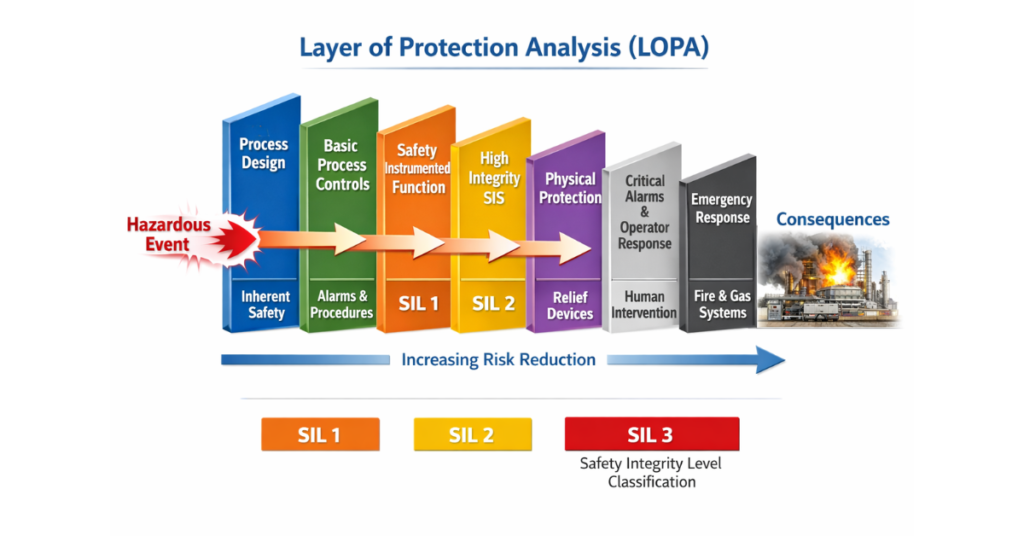
Layers of Protection Diagram
This diagram illustrates the Layers of Protection used in process safety management, representing a structured approach to risk reduction in industrial systems. Each concentric layer—from process design to plant emergency response—serves as a barrier against hazardous events. The image is particularly useful in LOPA (Layer of Protection Analysis) a Safety Integrity Level (SIL) study, where engineers assess whether existing safety measures are sufficient to reduce risk to a tolerable level. The SIS (Safety Instrumented System) layer shown in the diagram is directly linked to SIL, which quantifies the reliability required from automated safety functions when other layers may not fully mitigate the risk.

The diagram shows concentric circles, each representing a layer of protection around a process system. Here’s what each layer means:
1. Process Design (Innermost Layer)
- The core of the system.
- Includes inherent safety features like proper equipment selection, process control, and safe operating limits.
2. Basic Process Control System (BPCS)
- Automated control systems (e.g., DCS, PLC).
- Maintains normal operation and prevents deviations.
3. Alarms and Operators
- Human intervention based on alarms.
- Operators take corrective action when alerted.
4. Safety Instrumented System (SIS) / Emergency Shutdown (ESD)
- An independent system designed to take automatic action during hazardous events.
- Often designed according to SIL (Safety Integrity Level) standards.
5. Relief Devices
- Pressure relief valves, rupture discs.
- Protect against overpressure scenarios.
6. Physical Protection (e.g., Dikes)
- Physical barriers to contain spills or leaks.
- Prevents escalation to surrounding areas.
7. Plant Emergency Response (Outermost Layer)
- Firefighting, evacuation, medical response.
- Last line of defense when all other layers fail.
The Significance of the diagram with respect to the SIL classification study is provided below –

This post highlights the importance of understanding SIL classification methods and protection layers to ensure safe and reliable operations in the process industry. In my next article, I’ll explore the Risk Graph Method and Layer of Protection Analysis (LOPA)the two key approaches used to determine Safety Integrity Levels. Looking forward to receiving critical input and insights from all industry professionals to enrich the discussion and promote a stronger safety culture