Industrial fires and explosions are among the most destructive events in the process industries. A single incident can claim lives, devastate infrastructure, trigger environmental emergencies, and set a company back by years. Yet many of these events share recognisable patterns — predictable sequences of release, ignition, and escalation that process safety professionals can identify, model, and defend against.
This guide provides an in-depth look at the seven major industrial fire and explosion scenarios: pool fire, jet fire, flash fire, BLEVE, vapor cloud explosion (VCE), fireball, and dust explosion. Whether you are a process safety engineer, an HSE manager, a plant operator, or a student preparing for a NEBOSH or HAZOP certification, this resource will build your foundational understanding and support your day-to-day risk management work.
What Are Industrial Fire and Explosion Scenarios?
Industrial fire and explosion scenarios are hazardous events triggered by the unplanned release and ignition of flammable materials — gases, vapors, liquids, or combustible dusts. They occur across oil refineries, petrochemical plants, LNG terminals, pharmaceutical facilities, grain handling operations, and virtually any site where flammable materials are processed or stored.
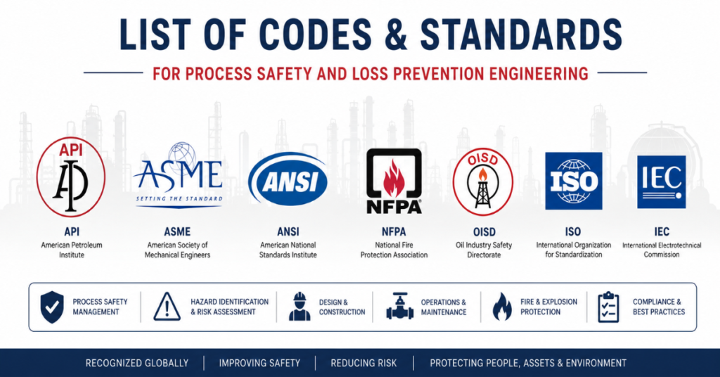
These scenarios are studied within the framework of Process Hazard Analysis (PHA), Quantitative Risk Assessment (QRA), and consequence modelling. Understanding them is a prerequisite for effective:
- Hazardous Area Classification (HAC)
- Emergency Response Planning
- Safety Instrumented System (SIS) design
- Separation distance and layout design
- Regulatory compliance (COMAH, OSHA PSM, PSSR)
Factors That Determine Severity
No two incidents are identical. The consequences of any fire or explosion depend on a combination of variables:
- Fuel type and properties — vapour pressure, flash point, heat of combustion
- Release rate and inventory size — how much material is involved
- Release pressure — determines jet velocity and atomisation
- Ignition timing — immediate ignition vs. delayed ignition leads to fundamentally different outcomes
- Congestion and confinement — critical for explosion overpressure generation
- Ventilation and atmospheric conditions — wind speed, stability, humidity affect cloud dispersion
- Proximity to personnel and assets — determines consequence severity
With that context established, let us examine each scenario in detail.
1. Pool Fire
What Is a Pool Fire?
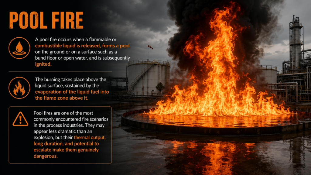
A pool fire occurs when a flammable or combustible liquid is released, forms a pool on the ground or on a surface such as a bund floor or open water, and is subsequently ignited. The burning takes place above the liquid surface, sustained by the evaporation of the liquid fuel into the flame zone above it.
Pool fires are one of the most commonly encountered fire scenarios in the process industries. They may appear less dramatic than an explosion, but their thermal output, long duration, and potential to escalate make them genuinely dangerous.
Common fuels: Crude oil, diesel, petrol (gasoline), kerosene, naphtha, condensate, solvents
How Does a Pool Fire Develop?
The typical sequence of events is:
- Liquid leak or spill (pipeline rupture, tank overflow, pump seal failure)
- Liquid spreads and forms a pool — pool area is limited by bunding, terrain, or free spread
- Vapour evaporates from the pool surface
- A competent ignition source contacts the vapour layer
- Sustained pool fire establishes with a visible flame above the liquid surface
The burn rate and flame height are determined by the fuel’s evaporation characteristics and the pool’s surface area. Larger pools produce more radiant heat and are harder to suppress.
Common Causes of Pool Fires
- Tank overfilling and overflow
- Pipeline or vessel rupture
- Flange or gasket leakage
- Pump mechanical seal failure
- Improper or blocked drainage systems
- Human error during transfer operations
Hazards of Pool Fires
Thermal radiation is the dominant hazard. Flames emit radiant heat in all directions, capable of causing first, second, and third-degree burns at significant distances. The thermal dose a person receives depends on the radiation intensity (kW/m²) and duration of exposure.
Structural weakening is a secondary but critical hazard. Steel begins to lose structural strength above 400–500°C. Prolonged pool fire exposure can cause columns, beams, and vessel skirts to fail, potentially collapsing equipment onto neighbouring infrastructure.
Escalation and domino effects are a major concern in congested plants. A pool fire beneath a pressure vessel can heat it to the point of BLEVE. Radiant heat may ignite secondary fuel sources, transforming a localised incident into a site-wide emergency.
Pool Fire Prevention and Protection
Engineering controls:
- Bund walls to limit pool spread and contain the fire footprint
- Sealed drainage systems that prevent flammable liquid from reaching unprotected areas
- Double-integrity seals on pumps and rotating equipment
Fire protection systems:
- Foam suppression systems (AFFF, FFFP) for hydrocarbon pool fires
- Fixed water deluge and monitor systems
- Automatic sprinkler systems in relevant areas
Detection systems:
- Fixed hydrocarbon point detectors and open-path gas detectors
- UV/IR flame detectors with fast response times
Passive fire protection (PFP):
- Intumescent and cementitious coatings on structural steel
- Fireproofing on vessel skirts and supports to delay structural failure
2. Jet Fire
What Is a Jet Fire?
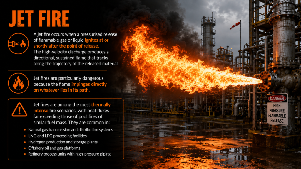
A jet fire occurs when a pressurised release of flammable gas or liquid ignites at or shortly after the point of release. The high-velocity discharge produces a directional, sustained flame that tracks along the trajectory of the released material. Jet fires are particularly dangerous because the flame impinges directly on whatever lies in its path.
Jet fires are among the most thermally intense fire scenarios, with heat fluxes far exceeding those of pool fires of similar fuel mass. They are common in:
- Natural gas transmission and distribution systems
- LNG and LPG processing facilities
- Hydrogen production and storage plants
- Offshore oil and gas platforms
- Refinery process units with high-pressure piping
Characteristics of Jet Fires
- Directionality: The flame follows the jet axis, meaning impingement is concentrated on whatever structure lies in its path rather than distributed as with pool fires.
- High heat flux: Jet fires can deliver localised heat fluxes of 200–350 kW/m² on impinged surfaces — sufficient to cause rapid vessel failure.
- Persistence: The fire continues for as long as the fuel source is pressurised and flowing. Isolation is the only way to extinguish it.
- Noise: High-velocity jet fires produce a characteristic roaring sound that can be an important early warning indicator.
Common Causes
- High-pressure pipeline rupture or guillotine failure
- Valve body or stem leakage
- Compressor or pump mechanical seal failure
- Small-bore instrument tubing or fitting failure
- Corroded or eroded piping in service
Hazards of Jet Fires
Equipment failure through direct impingement is the critical danger. A jet fire impinging on a pipeline, pressure vessel, or structural member can cause failure in minutes — far faster than the passive fire protection might be rated to withstand under such extreme localised flux.
Escalation to secondary explosions is a serious risk. If a jet fire impinges on a neighbouring vessel containing a liquefied gas, it may cause a BLEVE, dramatically expanding the consequence footprint.
Personnel hazards extend beyond the direct flame envelope. Radiant heat from a jet fire makes close-approach firefighting extremely dangerous, limiting the scope of emergency intervention.
Jet Fire Mitigation
- Emergency Shutdown (ESD) systems are the most effective response tool — rapidly isolating the source reduces flame duration and limits total heat output
- Blowdown systems depressurise and vent inventory to a flare or safe location, reducing the fuel available to sustain the fire
- Passive fire protection on structural steel and vessel skirts protects against failure during the early phase of emergency response
- Separation and layout — designing facilities to minimise the number of high-consequence assets within a jet fire’s potential reach
3. Flash Fire
What Is a Flash Fire?
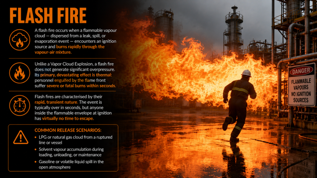
A flash fire occurs when a flammable vapour cloud — dispersed from a leak, spill, or evaporation event — encounters an ignition source and burns rapidly through the vapour-air mixture. Unlike a Vapor Cloud Explosion, a flash fire does not generate significant overpressure. Its primary, devastating effect is thermal: personnel engulfed by the flame front suffer severe or fatal burns within seconds.
Flash fires are characterised by their rapid, transient nature. The event is typically over in seconds, but anyone inside the flammable envelope at ignition has virtually no time to escape.
Common release scenarios:
- LPG or natural gas cloud from a ruptured line or vessel
- Solvent vapour accumulation during loading, unloading, or maintenance
- Gasoline or volatile liquid spill in the open atmosphere
The Difference Between a Flash Fire and a VCE
Both events start with a vapour cloud. The outcome depends critically on the degree of congestion and confinement at the ignition point:
- Open, uncongested area → flash fire (low overpressure, high thermal hazard)
- Congested or partially confined area → VCE (high overpressure, blast wave)
This distinction has major implications for consequence modelling and facility layout design.
Key Hazards
- Severe burn injuries — personnel within or near the flammable cloud envelope face life-threatening burns
- Secondary ignitions — the flame front may ignite adjacent equipment, structures, or secondary fuel sources
- Limited warning time — vapour clouds can be odourless or accumulate undetected before ignition
Flash Fire Prevention
- Fixed and portable gas detection systems to identify vapour clouds before ignition
- Adequate ventilation in process areas and enclosed spaces
- Strict ignition source control through permit-to-work systems
- Proactive leak detection and repair (LDAR) programmes
- Personal protective equipment — flame-resistant clothing (FRC) provides critical protection for personnel near potential flash fire zones
4. BLEVE — Boiling Liquid Expanding Vapor Explosion
What Is a BLEVE?
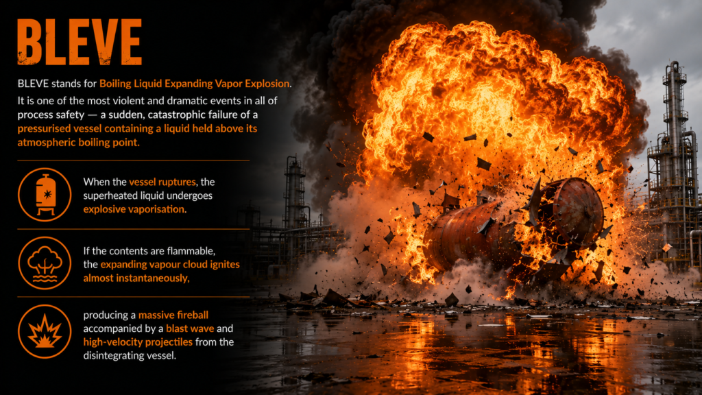
BLEVE stands for Boiling Liquid Expanding Vapor Explosion. It is one of the most violent and dramatic events in all of process safety — a sudden, catastrophic failure of a pressurised vessel containing a liquid held above its atmospheric boiling point.
When the vessel ruptures, the superheated liquid undergoes explosive vaporisation. If the contents are flammable, the expanding vapour cloud ignites almost instantaneously, producing a massive fireball accompanied by a blast wave and high-velocity projectiles from the disintegrating vessel.
Common materials involved: LPG (propane, butane), LNG, ethylene, ammonia, chlorine (non-flammable BLEVE — toxic release hazard)
How Does a BLEVE Occur?
The classic BLEVE sequence is:
- An external fire (commonly a pool fire or jet fire) heats the vessel shell
- Pressure inside the vessel rises as the liquid vapourises
- The vessel wall in the vapour space (above the liquid level) is heated without the cooling effect of the liquid and begins to weaken
- The vessel fails catastrophically at the weakened point
- Sudden pressure drop causes the superheated liquid to flash-vapourise instantaneously
- If the contents are flammable, the expanding vapour cloud ignites — producing a fireball
The speed of this sequence can be alarming. A heavily flame-impinged LPG vessel can fail within minutes if not cooled.
The Three Simultaneous Hazards of a BLEVE
A BLEVE is particularly dangerous because it delivers three distinct hazards at once:
1. Fireball A large, luminous sphere of burning vapour produces intense thermal radiation across a wide area. Fireball diameters from large LPG vessel BLEVEs have been measured at hundreds of metres.
2. Blast Wave The sudden pressure release generates an overpressure wave that causes structural damage, shatters windows, and injures or kills personnel.
3. Projectiles Vessel fragments — ranging from small shards to multi-tonne tank sections — become high-velocity missiles capable of travelling hundreds of metres from the point of failure. Historical incidents have recorded tank heads travelling over 600 metres.
Notable BLEVE Incidents
San Juanico, Mexico (1984): A series of BLEVEs at an LPG storage facility killed approximately 500–600 people and injured thousands more. It remains one of the deadliest industrial accidents in history.
Feyzin Refinery, France (1966): A cascade of BLEVEs following a propane leak killed 18 people and fundamentally influenced European process safety regulation.
Kingman, Arizona, USA (1973): A BLEVE during a rail car fire killed 11 firefighters and established that conventional firefighting approaches are ineffective against a BLEVE in progress.
BLEVE Prevention and Mitigation
- Water deluge systems — cooling vessel shells with water is the single most effective intervention; maintaining liquid coverage of the shell prevents localised overheating
- Pressure Relief Valves (PRVs) — allow controlled venting to prevent pressure from reaching failure levels
- Separation distances — adequate spacing between vessels limits the domino-effect potential of an adjacent fire
- Passive fire protection — intumescent coatings on vessel supports and skirts delay structural failure
- Emergency isolation and blowdown — rapidly reducing inventory limits the energy available for a BLEVE
5. Vapor Cloud Explosion (VCE)
What Is a Vapor Cloud Explosion?
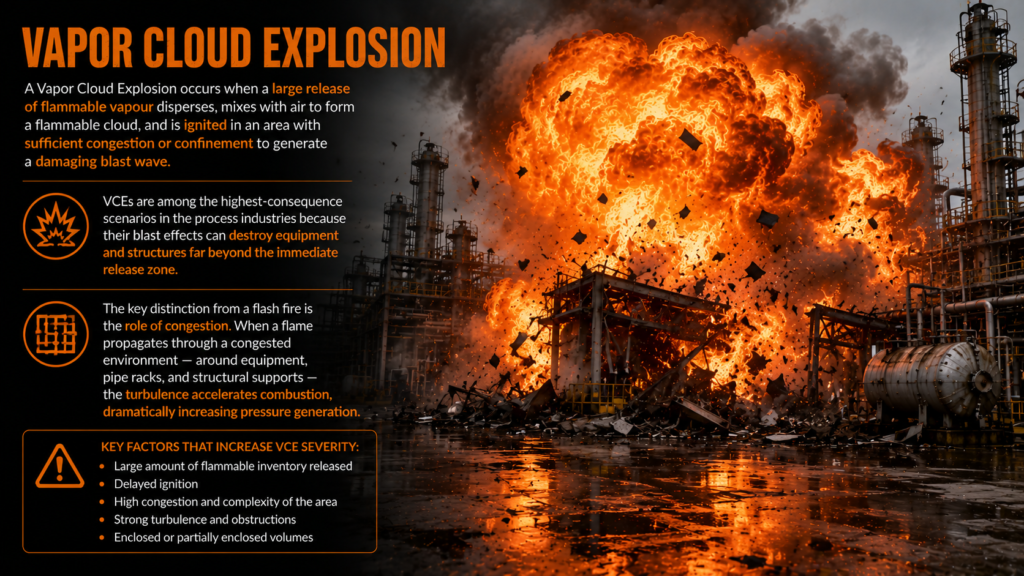
A Vapor Cloud Explosion occurs when a large release of flammable vapour disperses, mixes with air to form a flammable cloud, and is ignited in an area with sufficient congestion or confinement to generate a damaging blast wave. VCEs are among the highest-consequence scenarios in the process industries because their blast effects can destroy equipment and structures far beyond the immediate release zone.
The key distinction from a flash fire is the role of congestion. When a flame propagates through a congested environment — around equipment, pipe racks, and structural supports — the turbulence accelerates combustion, dramatically increasing pressure generation.
Conditions Required for a VCE
Four conditions must align for a VCE to occur:
- A sufficient release of flammable vapour or gas
- Delayed ignition — allowing the cloud to develop and travel
- Vapour-air mixture within the flammable range (between Lower Explosive Limit and Upper Explosive Limit)
- Ignition occurring in or near a congested or confined region
If ignition occurs immediately (as in a jet fire), or in an uncongested open area (as in a flash fire), the explosion potential is not realised.
Common fuels: Methane, propane, ethylene, hydrogen, BTEX compounds, refinery process streams
Hazards of VCE
Overpressure damage is the defining hazard. VCE blast waves can shatter control room glazing, collapse pipe racks, overturn vessels, and demolish process structures. Even relatively low overpressures (0.1–0.3 barg) can cause serious structural damage and injure people at considerable distances.
Secondary fires frequently follow VCEs. The blast ruptures additional pipelines and vessels, releasing further fuel that ignites in the post-explosion environment, creating a complex multi-hazard emergency scenario.
Structural collapse threatens personnel who survive the initial blast but are trapped beneath failed structures.
Notable VCE Incidents
Buncefield, UK (2005): A fuel storage tank overflow created a massive vapour cloud that detonated in the early morning. The explosion was felt over 100 miles away. Though there were no fatalities, the facility was largely destroyed, causing over £1 billion in damage.
Texas City Refinery, USA (2005): 15 workers were killed and 180 injured when a raffinate splitter column was overfilled, releasing a vapour cloud that exploded. The Baker Panel report that followed became a landmark document in process safety culture reform.
Flixborough, UK (1974): A bypass pipe failure released cyclohexane which exploded, killing 28 workers and destroying the site. Flixborough directly led to the UK’s CIMAH regulations and, later, COMAH.
VCE Prevention and Mitigation
- Rapid gas detection with a response strategy to isolate releases before a large cloud develops
- Minimising congestion in plant layout — separating equipment and avoiding complex pipe networks in congested bays
- Explosion-resistant control rooms — blast-rated buildings designed to protect personnel during a VCE
- Emergency isolation — ESD systems to rapidly stop fuel flow upon detection of a significant release
- Consequence modelling — using tools like PHAST, SAFETI, or FLACS during design to identify high-risk layout configurations
6. Fireball
What Is a Fireball?
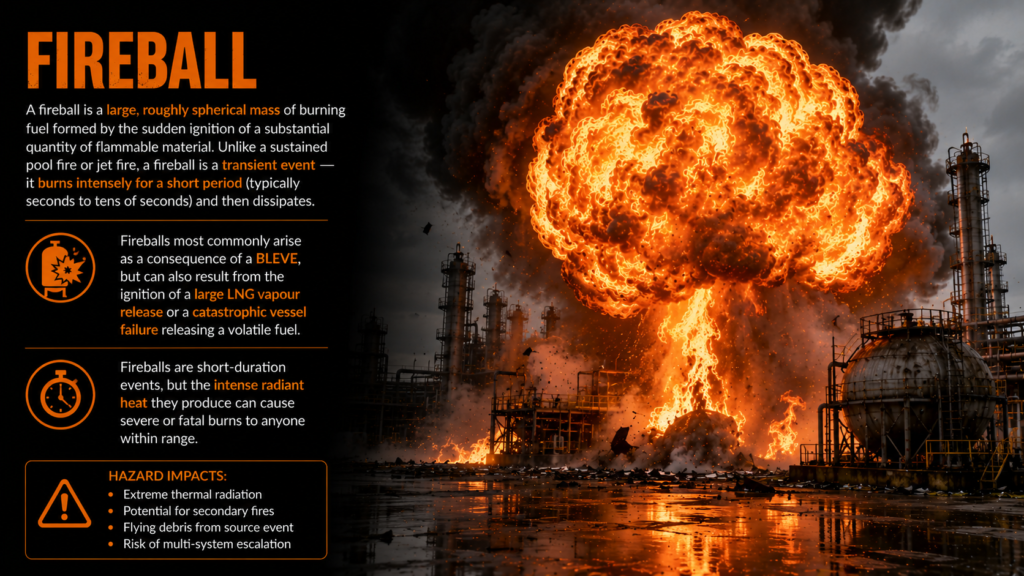
A fireball is a large, roughly spherical mass of burning fuel formed by the sudden ignition of a substantial quantity of flammable material. Unlike a sustained pool fire or jet fire, a fireball is a transient event — it burns intensely for a short period (typically seconds to tens of seconds) and then dissipates.
Fireballs most commonly arise as a consequence of a BLEVE, but can also result from the ignition of a large LNG vapour release or a catastrophic vessel failure releasing a volatile fuel.
Characteristics
- Diameter: Can reach hundreds of metres for large LPG or LNG releases
- Duration: Typically 5–30 seconds depending on fuel mass
- Thermal radiation: Extremely high peak intensity — the short duration is the key limiting factor in determining fatality zones
- Lift-off: As the fireball burns, buoyancy causes it to rise, which can expose a wider area to radiant heat
Fireball Hazards
Thermal burns at significant distances are the primary concern. The fireball’s radiant heat output is a function of its surface emissive power (SEP), diameter, and duration. Personnel within the thermal hazard zone can suffer fatal burns even without direct flame contact.
Ignition of secondary targets — nearby equipment, vegetation, or structures — can extend the incident.
Fireball Analysis in QRA
In Quantitative Risk Assessment, fireball modelling involves calculating:
- Fireball diameter — typically derived from empirical correlations based on fuel mass
- Duration — similarly fuel-mass dependent
- Surface emissive power (SEP) — the radiant output per unit area of the fireball surface
- Thermal dose — integrated heat flux over time, expressed in (kW/m²)⁴/³·s, used to derive probit-based injury and fatality probabilities
- Hazard distances — 1% fatality, 50% fatality, and 99% fatality contours used in risk mapping
These outputs feed directly into individual risk contours and societal risk (F-N curve) calculations for land-use planning and COMAH safety reports.
7. Dust Explosion
What Is a Dust Explosion?
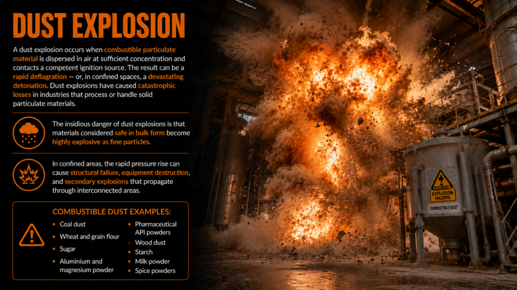
A dust explosion occurs when combustible particulate material is dispersed in air at sufficient concentration and contacts a competent ignition source. The result can be a rapid deflagration — or, in confined spaces, a devastating detonation. Dust explosions have caused catastrophic losses in industries that process or handle solid particulate materials.
The insidious danger of dust explosions is that materials considered safe in bulk form become highly explosive as fine particles. Coal, flour, sugar, aluminium, pharmaceutical powders, and wood dust have all been responsible for major incidents.
Combustible dust examples: Coal dust, wheat and grain flour, sugar, aluminium and magnesium powder, pharmaceutical API powders, wood dust, starch, milk powder, spice powders
The Dust Explosion Pentagon
A dust explosion requires five conditions to exist simultaneously. This is known as the Dust Explosion Pentagon:
- Fuel — the combustible dust itself
- Oxygen — normally present in air
- Ignition source — static electricity, hot surfaces, mechanical sparks, open flames
- Dispersion — dust suspended in air at a concentration between the Minimum Explosible Concentration (MEC) and the upper explosive limit
- Confinement — an enclosure that allows pressure to build
Remove any one element and the explosion cannot occur. This pentagon is the conceptual foundation of all dust explosion prevention strategies.
Primary and Secondary Explosions
Understanding the two-explosion sequence is critical to appreciating why dust explosions are so catastrophic:
Primary explosion: The initial ignition event — often relatively small — occurs in a piece of equipment such as a dust collector, mill, or conveyor enclosure.
Secondary explosion: The pressure wave and vibration from the primary explosion disturb settled dust layers on beams, ledges, ductwork, and floors — suspending them in air. This new cloud ignites from the still-burning primary event, creating a secondary explosion that may be many times larger and that propagates through an entire facility.
The secondary explosion is almost always the event that causes the greatest loss of life and structural damage. Good housekeeping directly attacks the fuel supply for secondary explosions.
Notable Dust Explosion Incidents
Imperial Sugar Refinery, USA (2008): An explosion and fire at a sugar processing facility killed 14 workers and injured 36. Accumulated sugar dust was identified as the primary fuel for catastrophic secondary explosions.
West Pharmaceutical Services, USA (2003): A polyethylene dust explosion killed 6 employees and injured 38, destroying the facility. The dust had accumulated in a concealed crawl space above a suspended ceiling.
Grain elevator explosions, USA (historical): Multiple incidents in grain handling facilities throughout the 20th century — driven by grain and corn starch dust — led to the development of NFPA 61 and OSHA’s Grain Handling Standard.
Dust Explosion Prevention and Mitigation
Prevention (removing one element of the pentagon):
- Housekeeping — regular cleaning of dust deposits on all surfaces, including elevated beams and ledges; the single most impactful preventive measure
- Inerting — replacing oxygen with nitrogen or CO₂ inside process equipment to remove the oxygen element
- Concentration control — dust suppression and local exhaust ventilation to keep dust concentrations below the MEC
- Ignition source control — grounding and bonding to eliminate static electricity, hot work permit systems, appropriate equipment selection for the dust zone
Mitigation (limiting consequences if prevention fails):
- Explosion venting (relief panels) — designed openings that direct the explosion pressure harmlessly to a safe external area, protecting the enclosure
- Explosion suppression systems — chemical suppression agents are deployed within milliseconds of explosion detection, extinguishing the event before full pressure develops
- Explosion isolation — rotary valves, chemical barriers, or fast-acting dampers that prevent flame and pressure from propagating through ductwork into adjacent areas
- Hazardous area classification for combustible dust environments — aligned with IEC 61241 / ATEX zone classification (Zone 20, 21, 22)
Summary Table: The Seven Major Industrial Fire and Explosion Scenarios
| Scenario | Trigger | Primary Hazard | Overpressure? | Key Prevention |
|---|---|---|---|---|
| Pool Fire | Liquid spill + ignition | Thermal radiation | No | Bunding, foam suppression, PFP |
| Jet Fire | Pressurised release + ignition | Direct flame impingement | No | ESD, blowdown, PFP |
| Flash Fire | Vapour cloud + ignition (open area) | Severe burns | Minimal | Gas detection, ignition control |
| BLEVE | Vessel failure + flammable contents | Fireball, blast, projectiles | Yes | Water deluge, PRVs, separation |
| VCE | Vapour cloud + ignition (congested) | Blast wave overpressure | Yes | Layout design, rapid isolation |
| Fireball | BLEVE or large vapour ignition | Thermal radiation (wide area) | Moderate | BLEVE/VCE prevention |
| Dust Explosion | Dust suspension + ignition | Primary + secondary blast | Yes | Housekeeping, venting, inerting |

Bringing It All Together: A Process Safety Perspective
These seven scenarios do not exist in isolation. In real incidents, one event frequently triggers another — a pool fire causes a BLEVE, a BLEVE creates a fireball and VCE conditions, and so on. This is the domino effect, and it is why consequence modelling must consider escalation pathways, not just the initiating event.
Effective process safety management addresses these scenarios at every level of the hierarchy of controls — from inherently safer design (reducing inventory, substituting less hazardous materials) through engineered safeguards (detection, isolation, deluge) to procedural controls (permit to work, training, emergency response planning).
Understanding these fire and explosion scenarios is not merely academic. It is the practical foundation on which safer facilities are designed, safer operations are run, and lives are protected.
For more process safety resources, industry insights, and HSE guidance, visit NitinJadhav.com.